Working from home, if new for an employee, can be difficult from a disruption perspective, especially if kids are involved. This post details how to create a simple busy/free indicator lamp that can be remotely controlled and shows red when busy, green when free, or off. Additionally, for added fun (if kids are involved), there is an RFID reader where you can scan the card from the outside of the box and the color (busy/free) will flash a few times indicating the current status. Because it’s remotely controlled, you can place this anywhere within WiFi reach and control it remotely from your phone, laptop, etc.
Pre-Baked Files
The scripts/functionality required for this post have been uploaded to this repository folder for ease of development - you can use this as a starting point during this tutorial when the respective code is referenced.
Parts Needed
This post assumes you can leverage constructing the programming board detailed in this previous post and use it for this tutorial. Therefore, the only remaining parts needed are:
- 1x ESP8266-01 (Black Board/1MB Flash = Main Controller)
- 1x ID-20 RFID Reader (Status Blink)
- 1x WS2812B LED Strip Lights (~20 LEDs in length)
- 1x 5V to 3.3V Logic Level Converter (RFID to ESP8266 UART)
- 3x 1kOhm Resistor
- 1x Piezo Buzzer (RFID Read Indicator - Audio)
- 1x LED (RFID Read Indicator - Visual)
- 1x Momentary Switch (ESP8266 Reset)
- 1x +3.3V Power Regulator (Buck Converter - ESP8266)
- 1x 5V Power Regulator (Buck Converter - RFID/LED Strip)
- 1x 12V 2A DC Adapter (Main Power)
- 1x Barrel Plug (Main Power Adapter Plug)
- 2x Heat Sinks (One for Each Power Regulator Chip)
- Breadboard(s)
- Circuit Wires
Theory of Operation
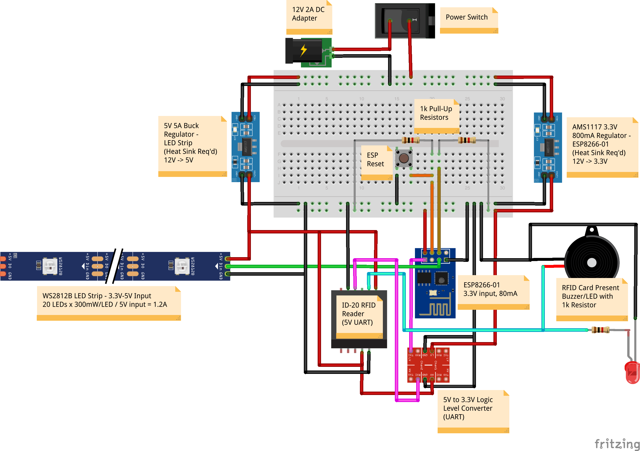
Incoming power for the entire circuit is a 12V 2A DC supply that is split between a 3.3V and 5V DC buck converter for voltage reduction. The 3.3V output serves to power the ESP8266-01, while the 5V output serves both the RFID reader and the WS2812B LED strip.
The main controller for this project is the ESP8266-01 microcontroller, which serves as a controller for the LEDs on/off/color, reader (UART) of the ID-20 RFID reader UART transmit, and web server. The web server component of the ESP8266-01 is used to serve the HTML content that can be used from a browser to remotely control the ESP8266-01 for things such as busy/free status, on/off, etc.
On boot, the ESP8266-01 connects to the local WiFi using the SSID/password specified in the loaded code. Once connected, it starts a web server listening on the IP it was given via DHCP from the local network it connected to, serving HTML content from the Serial Peripheral Interface Flash File System (SPIFFS) on the chip. It then continuously sends a multicast message containing its IP address for anyone on the local network attempting to discover the device endpoint (ease of discovery).
Once the IP is found using the multicast-address, visiting the IP in a web browser will result in the HTML content from the SPIFFS on the ESP8266-01 to be served/rendered, which contains HTML and JavaScript which displays a dynamic control interface for the busy/free indicator. This interface both sends messages back to the ESP8266-01 to update busy/free/on/off status (which the ESP8266-01 captures and adjusts the LED state/stores the state accordingly) and queries the ESP8266-01 endpoint for status updates to ensure that the web interface stays in sync with the state that the ESP8266-01 knows about (the source of truth). This latter part is useful in case the ESP8266-01 reboots or the web interface somehow gets out of sync with the source of truth, automatically adjusting the web interface to reflect what the actual state should be.
Lastly, there is an ID-20 RFID reader in the circuit to add a “fun” way to check status. It’s sometimes not desirable to leave the LED lights on for status updates, but it still may be helpful to have the circuit powered so someone can ad-hoc check the busy/free status. If the correct RFID (passive) card is passed over the reader in the box (top of the box in this design) and the ID of the card is correct (ID is configured in the ESP8266-01 code base), the LEDs will flash 3 times with either red or green LEDs, indicating busy or free, respectively. In addition, the LED and piezo buzzer attached to the RFID reader will flash and beep, respectively, indicating the card was read by the sensor. Since the ID-20 is a 5V device and the ESP8266-01 is a 3.3V device, there is a 5V to 3.3V logic level converter inline with the ID-20 Tx to ESP8266-01 Rx UART in order to convert the ID-20 5V UART signal to 3.3V, which is expected (and needed) by the ESP8266-01. Without this chip, unpredictable resets and/or burnout of the ESP8266-01 can occur.
Lastly, there is a script that can be run on a Linux/Unix/Mac-based system (anything with a bash shell) that automically listens for the multicast message from the ESP8266-01 and, when received, opens a Chrome web browser with the IP of the device. Assuming the script is run from a device on the same WiFi network (same SSID) and Chrome is installed, this is a very easy way to auto-launch the control interface.
Some important notes:
- The total circuit current required for all components is somewhere in the ~1.5A range (depending on how many LEDs are used, etc.). As such, ensure that your power adapter can accommodate this much current draw (which is why the 2A power supply is listed in the parts list).
- Make sure you place thermal paste and a heat sink on each of the 3.3V and 5V regulators - these devices emit a lot of heat due to the 12V power supply drop (or get a lower voltage DC supply, ensuring it still meets the >1.5A current requirements).
- The ESP8266-01 operates using 3.3V for both power and GPIO pins - while many online sites attempt to state that this device UART is 5V “tolerable”, do not attempt to run the RFID reader Tx to the ESP8266-01 Rx pin directly as this will result in undesirable/unpredictable resets of the ESP8266-01 or, worse, will burn the chip altogether.
Wiring Diagram
Below is the rendering of the wiring circuit for the project:
ESP8266-01 Control Logic
Programming the ESP8266-01 can be done via the instructions in the previous post mentioned at the beginning of this post, with the exception
of needing to set the SPIFFS settings in the Arduino application to be 1M (64k SPIFFS) instead of None as previously mentioned.
The following code creates the control logic, web server configuration, and other bits/pieces that make the circuit “go”. Ensure that you update the script with the SSID/password of your specific WiFi settings, and if you intend to use an RFID reader, ensure that the card ID matches the ID of your specific card (or expand the script if you wish to use multiple cards).
#include <ESP8266WiFi.h>
#include <ESPAsyncTCP.h>
#include <ESPAsyncWebServer.h>
#include <WiFiUdp.h>
#include <FS.h>
#include <WS2812FX.h>
#include <Ticker.h>

// USER CONFIGURATIONS //
const char* ssid = "<WIFI_SSID>";          // WiFi SSID (network name)
const char* passwd = "<WIFI_PASSWORD>";    // WiFi password
const char* expectedRFID = "0E008E9B5B40"; // ID of the RFID card used

// PROGRAM CONFIGURATIONS //
#define LED_PIN 2               // GPIO pin on ESP for LED control
#define LED_COUNT 20            // number of LEDs in LED strip
#define LED_BRIGHTNESS 128      // brightness of LEDs when lit
#define WIRELESS_TIMEOUT 10000  // timeout connecting to wifi triggering ESP reboot
#define SERVER_PORT 80          // web server port
#define UDP_PORT 1234           // port to advertise IP address on
#define ADVERTISE_SECONDS 3     // how often to advertise/send IP broadcast (seconds)
#define NUM_STATUS_BLINKS 3     // number of LED blinks on RFID status check
#define BROADCAST_ADDRESS IPAddress(255, 255, 255, 255) // broadcast address

// VARS //
String cardInput;        // raw input of RFID card ID (contains non-alphanumeric chars)
String cardID;           // string built with only alphanumeric components of card ID
WiFiUDP udp;             // UDP handler for broadcasting IP address
Ticker broadcastTicker;  // async timer for frequency of IP broadcast
int availableStatus = 1; // state management of LEDs (0=busy(red),1=free(green))
int powerStatus = 0;     // whether LEDs are on/off (0=off,1=on)

// INITIALIZATION //
AsyncWebServer server(SERVER_PORT);   // init web server
WS2812FX ws2812fx = WS2812FX(LED_COUNT, LED_PIN, NEO_GRB + NEO_KHZ800); // init LEDs

// FUNCTIONS //
// default 404/not found handling for web server
void notFound(AsyncWebServerRequest *request) {
  request->send(404, "text/plain", "Not found");
}

// advertise location of this availability device - advertised as:
//    AVAILABILITY:<IP_ADDRESS>:<WEB_SERVER_PORT>
void advertiseLocation() {
  String reachme = "AVAILABILITY:" + WiFi.localIP().toString() + ":" + SERVER_PORT + "\n";
  char msg[255];
  reachme.toCharArray(msg, 255);

  udp.beginPacketMulticast(BROADCAST_ADDRESS, UDP_PORT, WiFi.localIP());
  udp.write(msg);
  udp.endPacket();
}

// blink the current status known
void blinkStatus() {
  Serial.println("Blinking status...");
  static int frameCount;

  // calculate the number of times we should blink and do it
  frameCount = 0;
  ws2812fx.setMode(FX_MODE_BLINK);
  ws2812fx.start();
  while (true) {
    ws2812fx.service();

    if (ws2812fx.isFrame()) {
      frameCount++;

      // if we blinked enough, return to normal operation
      if (frameCount >= (NUM_STATUS_BLINKS*2)) {
        break;
      }
    }
  }

  Serial.println("Done blinking status");
  ws2812fx.setMode(FX_MODE_STATIC);

  // check if LEDs were off
  if (powerStatus == 0) {
    ws2812fx.stop();
  }
}

// connect to wifi
void connectWifi() {
  unsigned long start_of_connection = millis();
  while (WiFi.status() != WL_CONNECTED) {
    delay(500);
    Serial.print(".");

    if (millis() - start_of_connection > WIRELESS_TIMEOUT) {
      Serial.println();
      Serial.println("Exceeded wireless timeout - rebooting");
      ESP.reset();
    }
  }

  // print network and IP address lease
  Serial.println();
  Serial.print("Connected to: ");
  Serial.println(ssid);
  Serial.print("My IP address: ");
  Serial.println(WiFi.localIP());
}

// SETUP //
void setup() {
  // some startup things
  Serial.begin(9600);
  delay(500);
  Serial.println("\n\nInitializing...");

  // connect to wifi and obtain IP address
  WiFi.begin(ssid, passwd);
  Serial.print("Connecting to wireless SSID '");
  Serial.print(ssid);
  Serial.print("'");

  // connect to wifi
  connectWifi();

  // start SPIFFS to enable data storage of
  // the html, javascript, and style files
  if (!SPIFFS.begin()) {
    Serial.println("ERROR: Could not mount SPIFFS");
    return;
  }

  // initialize/set up the LED light strip
  Serial.println("Initializing the WS2812FX Light Strip...");
  ws2812fx.init();
  ws2812fx.setMode(FX_MODE_STATIC);
  ws2812fx.setColor(GREEN);  // free by default
  ws2812fx.setBrightness(LED_BRIGHTNESS);
  ws2812fx.stop();  // off by default
  Serial.println("Light strip set up.");

  // set up some routes
  server.on("/", HTTP_GET, [](AsyncWebServerRequest *request) {
    Serial.println("Received GET request at '/'");
    request->send(SPIFFS, "/index.html");
  });

  server.on("/power", HTTP_GET, [](AsyncWebServerRequest *request) {
    Serial.println("Received GET request at '/power'");
    request->send(200, "text/plain", String(powerStatus));
  });

  server.on("/status", HTTP_GET, [](AsyncWebServerRequest *request) {
    Serial.println("Received GET request at '/status'");
    request->send(200, "text/plain", String(availableStatus));
  });

  server.on("/power", HTTP_POST, [](AsyncWebServerRequest *request) {
    Serial.println("Received POST request at '/power'");
    String message;

    if (request->hasParam("message", true)) {
      message = request->getParam("message", true)->value();
      Serial.println("...Received content: " + message);

      if (message == "0") {
        Serial.println("Requested Power Off");
        powerStatus = 0;
        ws2812fx.stop();
      } else if (message == "1") {
        Serial.println("Requested Power On");
        powerStatus = 1;
        ws2812fx.start();
      } else {
        Serial.println("Unknown state requested!");
      }
    } else {
      Serial.println("...No content received");
    }
  });

  server.on("/status", HTTP_POST, [](AsyncWebServerRequest *request) {
    Serial.println("Received POST request at '/status'");
    String message;

    if (request->hasParam("message", true)) {
      message = request->getParam("message", true)->value();
      Serial.println("...Received content: " + message);
      if (message == "0") {
        Serial.println("Requested Busy");
        availableStatus = 0;
        ws2812fx.setColor(RED);
      } else if (message == "1") {
        Serial.println("Requested Free");
        availableStatus = 1;
        ws2812fx.setColor(GREEN);
      } else {
        Serial.println("Unknown state requested!");
      }
    } else {
      Serial.println("...No content received");
    }

    request->send(200, "text/plain", "");
  });

  // bind 404/not found handler
  server.onNotFound(notFound);

  // start the server (async - does not use even loop "loop()")
  server.begin();

  // set up ability to advertise location information
  // every XX seconds to avoid over-advertising in loop
  // and/or adding a delay/sleep in loop which would delay
  // the functionality of the LED strip
  broadcastTicker.attach(ADVERTISE_SECONDS, advertiseLocation);
}

// LOOP //
void loop() {
  // accommodate if ESP loses wifi connectivity - attempt to reconnect
  if (WiFi.status() != WL_CONNECTED) {
    connectWifi();
  }

  // read values from the RFID reader
  if (Serial.available() > 0) {
    cardID = "";
    cardInput = "";

    // read all characters for message
    cardInput = Serial.readString();
    Serial.print("Card Input (RAW): ");
    Serial.println(cardInput.substring(0));

    // parse only ID components/remove garbage chars
    for (int i = 0; i < cardInput.length(); i++) {
      if (isalnum(cardInput[i])) {
        cardID += cardInput[i];
      }
    }

    // check if card matches our expected ID - if so, take action
    if (cardID == expectedRFID) {
      Serial.print("Received Expected RFID Card ID: ");
      Serial.println(cardID);

      blinkStatus();
    } else {
      Serial.print("Received Unexpected RFID Card ID (ignoring): '");
      Serial.println(cardID);
    }
  } else {
    // drive the LED strip
    ws2812fx.service();
  }
}
To make the above script compile, the following libraries also need to be included with your project - these can be zipped from their GitHub source (instead of cloning the source code, use the “download zip” option) and the zip dropped directly into the root directory of the Arduino project folder:
ESPAsyncTCP-master.zipESPAsyncWebServer-master.zip
In addition, install the WS2812FX library using the Tools -> Manage Libraries functionality of the Arduino application.
ESP8266-01 Web Content
In addition, the web content needs to be uploaded to the SPIFFS location on the ESP8266-01 so that the web server can serve the content. To
do this, you need to install the Arduino ESP8266 Filesystem Uploader for the Arduino
application. Follow the instructions for how to manage the SPIFFS content, but in summary, it requires creating a data directory in your
Arduino project folder and placing files within it/uploading them using this tool, ensuring that the Serial Monitor is not enabled when
uploading as the tool uses the same Serial circuit. The following is the index.html file that was used in the data/ directory of this
project - it serves as the web-based control interface for the project:
<html lang="en">
  <head>
    <meta charset="utf-8">
    <meta name="viewport" content="width=device-width, initial-scale=1, shrink-to-fit=no">

    <link rel="stylesheet" href="https://maxcdn.bootstrapcdn.com/bootstrap/4.0.0/css/bootstrap.min.css" integrity="sha384-Gn5384xqQ1aoWXA+058RXPxPg6fy4IWvTNh0E263XmFcJlSAwiGgFAW/dAiS6JXm" crossorigin="anonymous">

    <title>Status Controller</title>

    <style type="text/css">
      .container {
        text-align: center;
      }

      .power-status-indicator #power-status span.badge,
      .status-indicator #status span.badge {
        width: 200px;
        font-size: 16px;
        padding: 6px 0px;
      }

      #power-adjuster .btn,
      #status-adjuster .btn {
        width: 100px;
      }
    </style>
  </head>
  <body>
    <div class="container">
      <h1 class="main-header">Busy/Free Indicator</h1>
      <div class="tool-explanation">
        Controller for indicating busy/free.
      </div>

      <div class="power-status-indicator mt-2">
        <span class="status-label mr-1 font-weight-bold">Power Status:</span>
        <span id="power-status">
          <span class="badge badge-light">Querying...</span>
        </span>
      </div>

      <div class="status-indicator mt-2">
        <span class="status-label mr-1 font-weight-bold">Availability Status:</span>
        <span id="status">
          <span class="badge badge-light">Querying...</span>
        </span>
      </div>

      <div id="power-adjuster" class="mt-2">
        <button type="button" id="set-off" class="btn btn-outline-secondary mr-2">Off</button>
        <button type="button" id="set-on" class="btn btn-outline-success mr-2">On</button>
      </div>

      <div id="status-adjuster" class="mt-2">
        <button type="button" id="set-free" class="btn btn-outline-success mr-2">Free</button>
        <button type="button" id="set-busy" class="btn btn-outline-warning">Busy</button>
      </div>
    </div>

    <script src="https://code.jquery.com/jquery-3.5.1.min.js" integrity="sha256-9/aliU8dGd2tb6OSsuzixeV4y/faTqgFtohetphbbj0=" crossorigin="anonymous"></script>
    <script src="https://cdnjs.cloudflare.com/ajax/libs/popper.js/1.12.9/umd/popper.min.js" integrity="sha384-ApNbgh9B+Y1QKtv3Rn7W3mgPxhU9K/ScQsAP7hUibX39j7fakFPskvXusvfa0b4Q" crossorigin="anonymous"></script>
    <script src="https://maxcdn.bootstrapcdn.com/bootstrap/4.0.0/js/bootstrap.min.js" integrity="sha384-JZR6Spejh4U02d8jOt6vLEHfe/JQGiRRSQQxSfFWpi1MquVdAyjUar5+76PVCmYl" crossorigin="anonymous"></script>
  </body>

  <script type="text/javascript">
    // send request to update status
    function changeStatus() {
      var action;
      switch($(this).attr("id")) {
        case "set-busy":
          action = 0;
          break;
        case "set-free":
          action = 1;
          break;
      }

      // perform an ajax request against the server to adjust state
      $.ajax({
        'url' : '/status',
        'type' : 'POST',
        'data' : { 'message' : action }
      });

      // ensure the UI is aligned to the selected action
      // this is safe because the next call is a query to the server
      // to inquire about the state/will adjust the UI if out of sync
      alignStatusButtons(action);
      alignStatusLabel(action);
    }

    // send request to adjust power
    function changePower() {
      var action;
      switch($(this).attr("id")) {
        case "set-off":
          action = 0;
          break;
        case "set-on":
          action = 1;
          break;
      }

      // perform an ajax request against the server to adjust power
      $.ajax({
        'url' : '/power',
        'type' : 'POST',
        'data' : { 'message' : action }
      });

      // ensure the UI is aligned to the selected action
      // this is safe because the next call is a query to the server
      // to inquire about the state/will adjust the UI if out of sync
      alignPowerButtons(action);
      alignPowerLabel(action);
    }

    // function that will handle status of power buttons
    function alignPowerButtons(statusCode) {
      // reset all buttons
      $("#power-adjuster button")
        .removeAttr("disabled")
        .removeClass("active");

      // activate the button based on the power status
      switch(statusCode) {
        case 0:
          $("#power-adjuster button#set-off").attr("disabled", "disabled").addClass("active");
          break;
        case 1:
          $("#power-adjuster button#set-on").attr("disabled", "disabled").addClass("active");
          break;
      }
    }

    // function that will handle status of status buttons
    function alignStatusButtons(statusCode) {
      // reset all buttons
      $("#status-adjuster button")
        .removeAttr("disabled")
        .removeClass("active");

      // activate the button based on the status
      switch(statusCode) {
        case 0:
          $("#status-adjuster button#set-busy").attr("disabled", "disabled").addClass("active");
          break;
        case 1:
          $("#status-adjuster button#set-free").attr("disabled", "disabled").addClass("active");
          break;
      }
    }

    // function to update the power status label
    function alignPowerLabel(statusCode) {
      switch(statusCode) {
        case 0:
          $("#power-status").html('<span class="badge badge-secondary" set="0">Off</span>');
          break;
        case 1:
          $("#power-status").html('<span class="badge badge-success" set="1">On</span>');
          break;
        case 2: // unknown status
          $("#power-status").html('<span class="badge badge-danger">Fail (Unknown Status)</span>');
          break;
        case 3: // communication error
          $("#power-status").html('<span class="badge badge-danger">FAIL (Comm Error)</span>');
          break;
      }
    }

    // function to update the availability status label
    function alignStatusLabel(statusCode) {
      switch(statusCode) {
        case 0:
          $("#status").html('<span class="badge badge-warning" set="0">Busy</span>');
          break;
        case 1:
          $("#status").html('<span class="badge badge-success" set="1">Free</span>');
          break;
        case 2: // unknown status
          $("#status").html('<span class="badge badge-danger">Fail (Unknown Status)</span>');
          break;
        case 3: // communication error
          $("#status").html('<span class="badge badge-danger">FAIL (Comm Error)</span>');
          break;
      }
    }

    // function to update the status indicators every X seconds
    // to ensure the web interface is always in sync
    setInterval(function ( ) {
      // perform an ajax request against the server to adjust power state
      $.ajax({
        url: '/power',
        type: 'GET',
        timeout: 1000,
        success: function(data, status, xhr) {
          // only update if there has been a change
          var statusDiv = $("#power-status");
          if (statusDiv.first("span.badge").attr("set") != data) {
            switch(data) {
              case "0": // Off
                alignPowerButtons(0);
                alignPowerLabel(0);
                break;
              case "1": // On
                alignPowerButtons(1);
                alignPowerLabel(1);
                break;
              default:  // Something went wrong/comm error
                console.log("Received unknown state: " + this.responseText);
                alignPowerLabel(3);
            }
          }
        },
        error: function(jqXhr, textStatus, errorMessage) {
          alignPowerLabel(4);
        }
      });

      // perform an ajax request against the server to adjust availability state
      $.ajax({
        url: '/status',
        type: 'GET',
        timeout: 1000,
        success: function(data, status, xhr) {
          // only update if there has been a change
          var statusDiv = $("#status");
          if (statusDiv.first("span.badge").attr("set") != data) {
            switch(data) {
              case "0": // Busy
                alignStatusButtons(0);
                alignStatusLabel(0);
                break;
              case "1": // Free
                alignStatusButtons(1);
                alignStatusLabel(1);
                break;
              default:  // Something went wrong/comm error
                console.log("Received unknown state: " + this.responseText);
                alignStatusLabel(2);
            }
          }
        },
        error: function(jqXhr, textStatus, errorMessage) {
          alignStatusLabel(3);
        }
      });
    }, 3000 ) ;

    // bind the buttons
    $(document).ready(function() {
      $("#status-adjuster button").bind("click", changeStatus);
      $("#power-adjuster button").bind("click", changePower);
    });
  </script>
</html>
Note: When attempting to upload the data using the data uploader tool, ensure your ESP8266-01 is in programming mode - if you previously programmed the chip with the control logic, the chip will attempt to go back into the main loop cycle of the program (if using the programmer mentioned in the previous post). Failure to close the Serial Terminal or reset the ESP8266-01 into programming mode will result in a failure to upload the web content.
Auto Discovery Script
As mentioned, the auto-discovery script can be used to listen for the multicast message and automatically open a browser with the web-based
controller. The script is fairly straightforward, and expects the message received to be of the format
AVAILABILITY:<ENDPOINT_IP>:<ENDPOINT_PORT>, where:
AVAILABILITY: Indicates this message came from the busy/free availability circuit (in case there are other multicast broadcasts).<ENDPOINT_IP>: IP address that the ESP8266-01 web server is listening on/serving content from.<ENDPOINT_PORT>: Port that the ESP8266-01 web server is listening on/serving content from.
The following is the script used for auto-discovery:
#!/bin/bash
#
# Listens for UDP message broadcast on a port and if the message
# matches the signature of what's expected for the status indicator,
# it opens the control UI of the indicator in a Chrome browser.

# which port to listen for broadcasts on
LISTEN_PORT=1234

echo "Status controller UI launcher"

while true; do
  echo "Listening for broadcast..."
  availability=$(nc -ul $LISTEN_PORT -w 0)

  echo "Received broadcast: " $availability
  echo "Parsing components..."
  OIFS=$IFS
  IFS=':'
  read -ra MSG <<< "$availability"
  IFS=$OIFS

  echo "Determining next course of action..."
  if [ "${MSG[0]}" == "AVAILABILITY" ]; then
    endpointIp="${MSG[1]}"
    endpointPort="${MSG[2]}"

    if [ -z "${endpointIp}" ]; then
      echo "Message is missing IP address"
    elif [ -z "${endpointPort}" ]; then
      echo "Message is missing port number"
    else
      echo "Found endpoint: ${endpointIp}:${endpointPort}"
      echo "Opening in Chrome..."
      /usr/bin/open -a "/Applications/Google Chrome.app" "http://${endpointIp}:${endpointPort}"
      break
    fi
  else
    echo "Message '${availability}' did not match expected format - likely a different broadcast"
  fi
done
Usage
To use the busy/free indicator, simply power it on, and launch the “auto discovery” script from a device on the same WiFi network as the busy/free circuit. If all goes well, the script will detect the multicast message and launch a browser session (Chrome) that will have the busy/free control web interface served from the ESP8266-01 that you can use to control the remote device!
As an improvement, you might consider expanding the ESP8266-01 functionality to automatically update itself based on busy/free in your Google or Outlook calendars, using the calendar APIs to check whether your have meetings planned/are in a meeting.
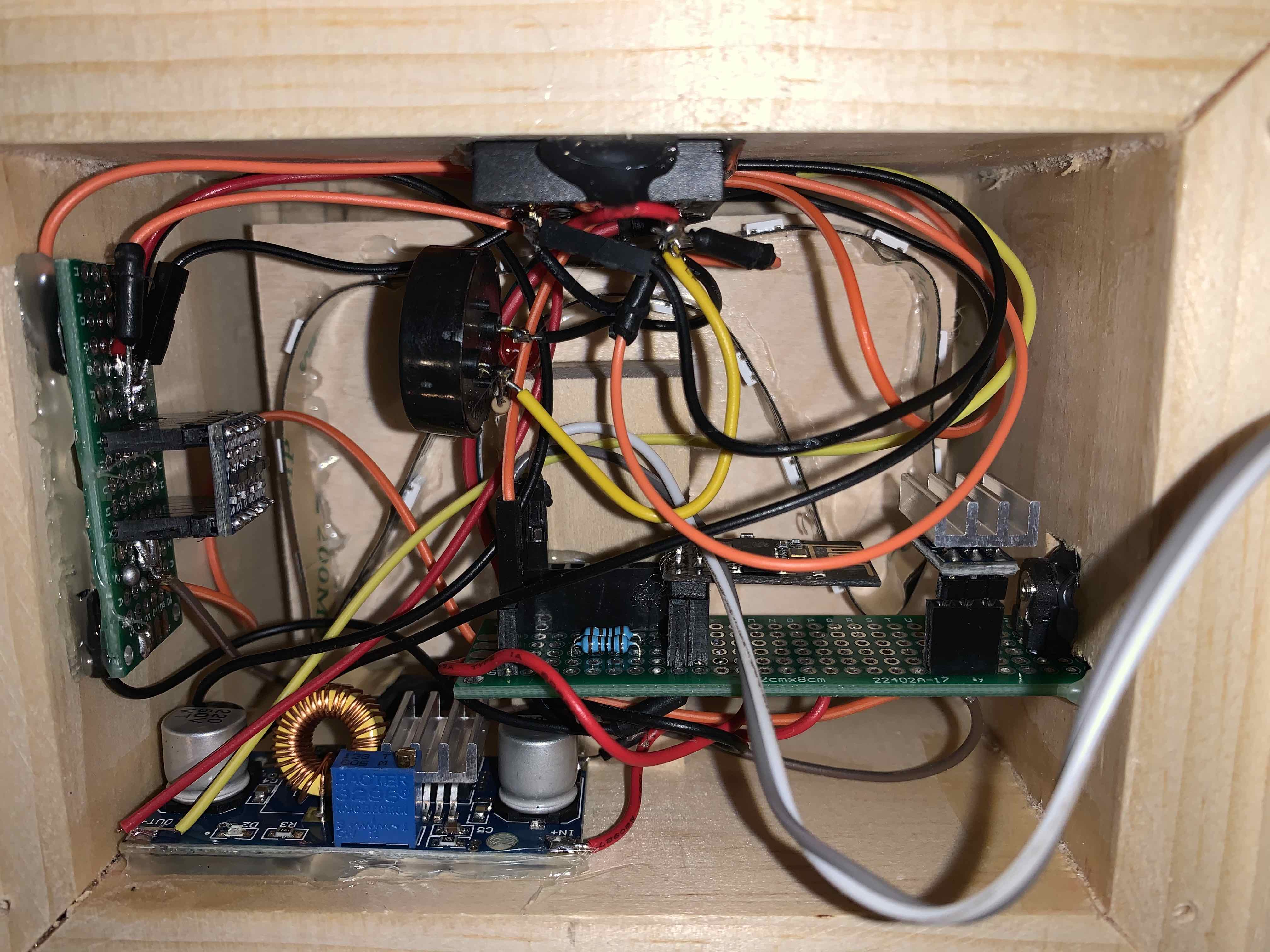
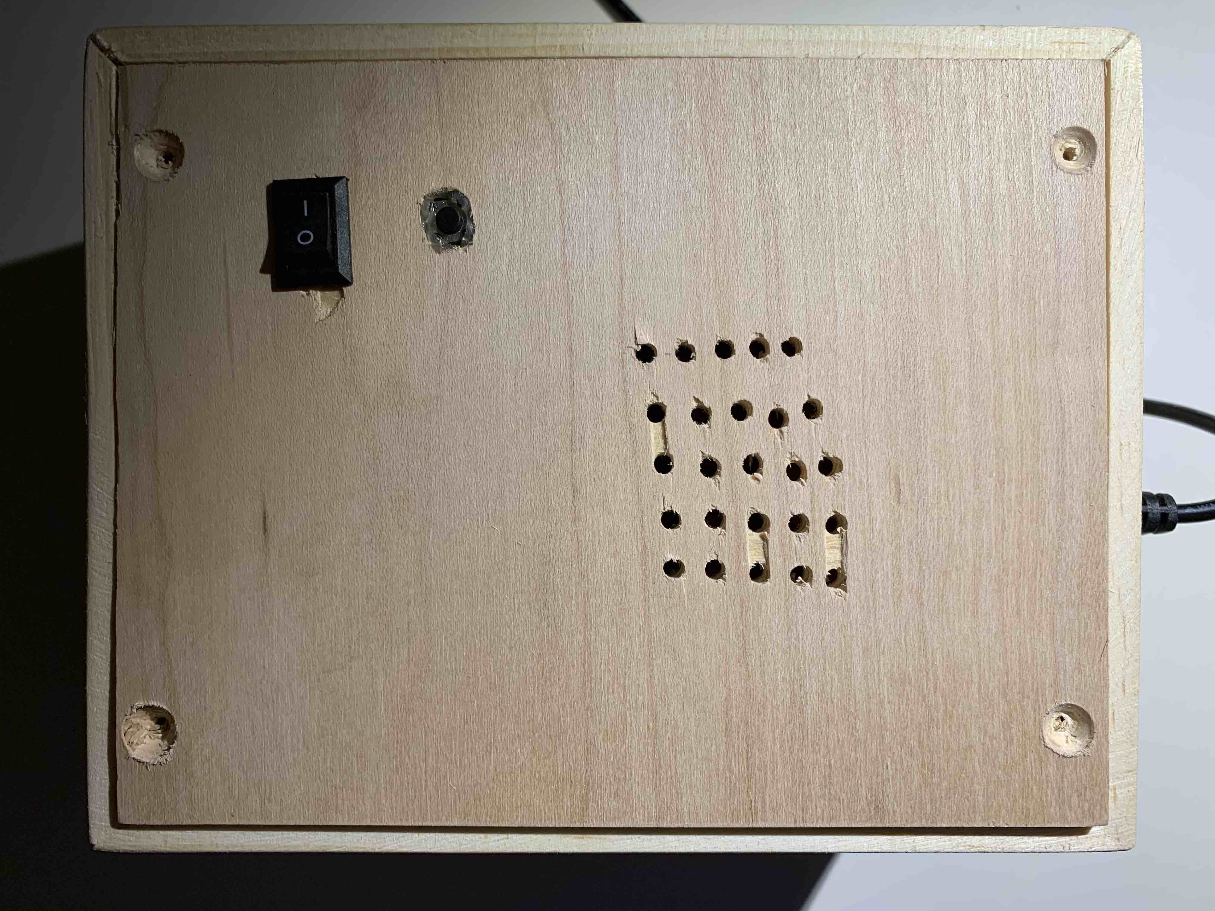
Wooden Project Enclosure
A wooden box was created to house the various electronics and display the busy/free LEDs. This box was just a scrap to contain the circuit components and any project enclosure (with enough holes for heat dissipation of the voltage regulators) will work. As a note, the circuit components shown in the back are not pretty/need some tidying, but it was a first attempt to get things packaged up for use/testing.

Shortcomings
There is a small bug where if the RFID card is presented to the ID-20 RFID reader several times, the ESP8266-01 web server becomes unresponsive. The control chip is not entirely unresponsive (the RFID control of the LEDs continues to work), but the control interface loses its connection and you can no longer control the busy/free controller remotely. This happens at random, and needs to be investigated (possibly with outputs to the serial monitor of the Arduino software when the RFID chip is being scanned to see what is actually occurring).
In addition, the code base could use some best practices/refactoring, the wooden enclosure could be much more refined, and the wiring/layout in the enclosure needs some tidying. However, this is the baseline for a larger initiative if time permits.
Credit
The above tutorial was pieced together with some information from the following sites/resources, among others that were likely missed in this list: