This post is an attempt to detail how to use (and program) an ESP8266 wifi board with a DHT22 temperature/humidity sensor to send data to an endpoint running Graphite and Statsd for routine metric collection of temperature and humidity data. It builds on this previous post which configures a Raspberry Pi 3 B+ as a central Graphite, Statsd, and Grafana endpoint and forms the basis of a wireless, cheap sensor network.
Parts Needed
This tutorial utilizes the following parts and software:
- 1x ESP8266-01 (Black Board/1MB Flash)
- 1x FTDI (Serial to USB) Converter Board with USB Cable
- 2x 1k-Ohm Resistors
- 1x +3.3V External Power Supply
- 2x Momentary Buttons
- Breadboard
- Circuit Wires
- Arduino IDE
- 1x ESP8266-01 Breakout Board (Optional)
WARNING: It is recommended that you utilize an external +3.3V power supply and not the VCC from the FTDI (Serial to USB) board to power the ESP8266. The ESP8266 chip can consume quite a bit of power during wifi operations and for clean power and avoiding unexpected issues, a solid/steady +3.3V power supply is recommended. In no circumstances should you use a +5V source as this will almost certainly fry/destroy the ESP8266 board.
ESP8266-01 Initial Wiring and Testing
First and foremost, because I had so much difficulty being able to program the ESP8266-01 device, we’ll describe how to correctly wire and program the ESP8266-01 device using the Arduino IDE. There is a generally decent forum for support of the ESP8266 here but getting all of the flash settings correct for the board type as well as the baud rate (which apparently varies widely depending on what type of board you receive and from which manufacturer). This tutorial will be using the ESP8266-01 device with the black board which has 1MB of flash memory (not the blue board, which has 512kB of flash memory). There are a few different ways to flash the board, and by default the board comes pre-loaded with AT-controllable software which is pretty old-fashioned. The first is via using the command-line utility esptool.py, while the second is using the Arduino IDE to flash the device with the code you wish to program the board with. We will focus on the latter (Arduino IDE) as it is more user friendly.
Wiring
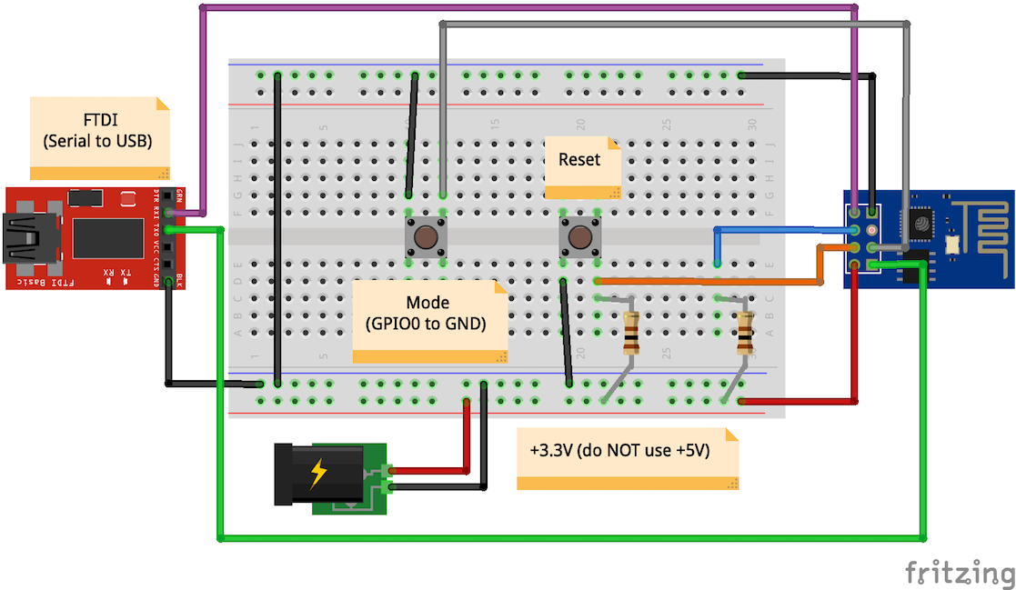
First, the wiring. In order to program the board, it’s best to find a breakout board which allows you to align the pins on the ESP8266-01 with a breadboard-expected layout as the pins are generally configured in a non-friendly way for breadboards. There are 2 modes of operation for the device, as explained below:
- Flash (Programming) Mode: This is the mode which is required for flashing the device with the specific firmware or program you wish to load. In order to obtain this mode, you must wire the GPIO0 pin to ground on boot/reset of the device.
- Normal (Operating) Mode: In normal mode, the device starts and loads the firmware already in flash. This is what you should expect under normal operating circumstances. For this mode, ensure the GPIO0 pin is not wired to GND.
In order to simplify the programming process, I built a simple circuit which enables a reset and flash-programming button to avoid needing to unhook-rehook wires during flashing mode, as seen below:
Testing Communication
A quick test of the board can be done through the Arduino IDE without much effort. Open the Arduino IDE and configure the IDE to communicate with the board over the USB port configured by navigating to Tools -> Port, and selecting the USB port for the ESP8266 (for the MacBook Pro I was running this on, it showed up as “/dev/cu.usbserial-A5011U4E). Next, open the Serial Monitor (Tools -> Serial Monitor). Most sites/sources will inform you that the ESP8266-01 communicates over serial using a baud rate of 115200 - however, most of the boards I received with the AT firmware communicated using 74480 baud. Select your baud setting from the drop-down, and ensure “Both NL & CR” is selected from the drop-down for newline options. In order to put the board into programming mode, hold the GPIO0 GND button down, click the Reset button, release the Reset button, and then release the GPIO GND button. This essentially reboots the chip with GPIO0 in GND mode, placing the chip into programming mode - you should have seen a blue light flash on the board and something similar to the following output in the serial terminal:
ets Jan 8 2013,rst cause:2, boot mode:(1,7)
This is the correct output to expect when the board is in programming mode and reset. Next, let’s reboot the board into normal operating mode - simply click and release the Reset button (don’t touch the GPIO GND button) and you should again see a blue flash on the board and output in the serial terminal indicating checksum checks, etc. This is indicative of the firmware loading and the board moving into normal operating mode.
Programming Board
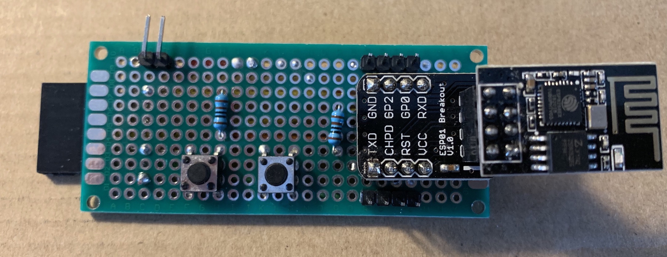
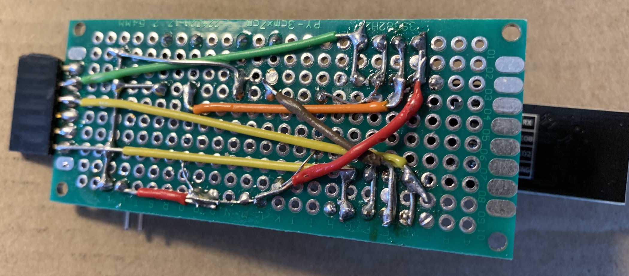
After putting together a breadboard to support the programming, I decided to wire and solder a more solid/permanent programming board that would enable plugging in a +3.3V power source as well as plug the FTDI serial to USB converter board directly in. The wiring isn’t pretty, but it’s been a while since I’ve soldered.
Front
Back
Blinking LED (Hello World)
Next we will configure the Arduino IDE to communicate with and program the ESP8266-01. First, follow the instructions here to enable the ESP8266 board within the Arduino IDE. At the time of this tutorial, I installed version 2.4.2 (stable) for the ESP8266 board library.
Select the “Generic ESP8266 Module” from the Tools -> Boards menu.
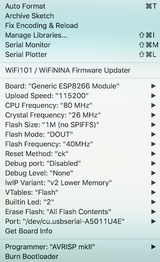
Next, we will configure the Arduino IDE with the correct settings to flash the board. It took a long while to figure out the correct settings, and it’s essential that you get these correct in order to get the correct loading of the firmware onto the board or else you will undoubtedly see what appears to be a successful load but when you go to run the board firmware it will show with checksum errors for what appears to be no reason at all. Here is a screen shot of the settings needed (these are configured in the “Tools” menu):
The main settings that needed to be changed at the time of this tutorial were the following (but definitely validate all settings):
- Upload Speed: 115200
- CPU Frequency: 80 MHz
- Crystal Frequency: 26 MHz
- Flash Size: 1M (no SPIFFS)
- Flash Mode: DOUT <– this one was tricky
- Flash Frequency: 40MHz
Once configured, you should be ready to test the module. A simple first test is to flash the on-board LED, which has an example sketch you can use under File -> Examples -> ESP8266 -> Blink. First, ensure your ESP8266 is in programming/flash mode (recall, hold the GPIO0 to GND button, then reset the chip). Then, load this example and flash it to the chip by clicking the “Upload” button on he IDE. This will take a minute or two with a progress bar. Once complete, if all goes well, you should see the blue LED on the board start to blink. If you press the reset button without holding the GPIO0 to GND button, you should again see the LED start to blink, indicating the ESP8266 has been successfully flashed with your example firmware and is operating in normal mode.
Congratulations, you’re ready to move on!
ESP8266 Temperature Sensor
Now that we have the basics down, we’ll expand the wiring and create a small program that parses a DHT22 temperature and humidity sensor and prints values to the serial console. This is the first step in the longer-term objective for sending the metric information to a centralized time-series database.
UPDATE: Since the initial post, I discovered that there is a workaround for most sensor libraries not correctly initializing the DHT22 sensor on setup. Thanks to this comment on the GitHub repository for the Adafruit firmware, updates have been made to the circuit and corresponding firmware to adjust for the following, ensuring the DHT22 works every time:
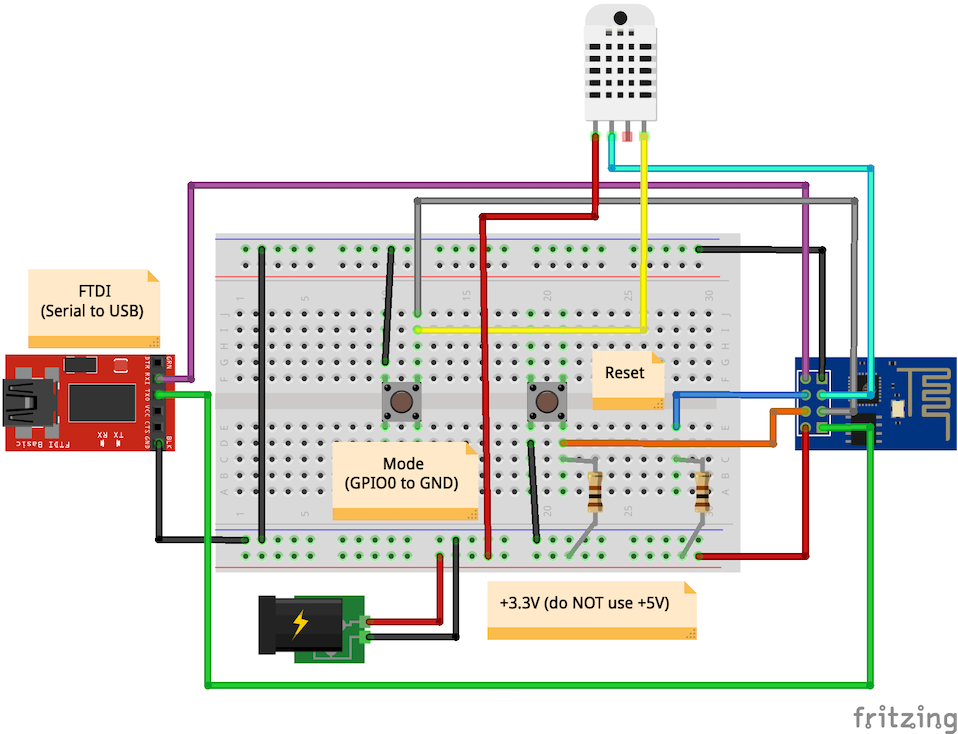
- Wire the DHT22 GND to GPIO0.
- Wire the DHT22 DATA to GPIO2.
- Update firmware to initialize the sensor by correctly sending GND to true GND for duration of time.
Temperature Sensor Wiring
First, the circuit wiring. We will use our programming circuit as a starting point for expanding the wiring for the sensor:
Temperature Sensor Sketch
In order to interact with the temperature sensor, the Arduino sketch needs to include the libraries to do so. The library we will use is from the Adafruit library:
To get this library into the Arduino IDE, first download the entire repository from the “Clone or download” (green button) link on the GitHub page and select “Download ZIP”. Then, in the Arduino IDE, navigate to Sketch -> Include Library -> Add .ZIP Library… and select the library to load it into the Arduino IDE.
Next, we’ll create the software to perform the read and write the output to the Serial console. Copy/paste the following code to your Sketch file:
// based on the example script here: https://github.com/adafruit/DHT-sensor-library/blob/master/examples/DHTtester/DHTtester.ino

#include <DHT.h>

// configuration settings
#define DHTPIN     2  // ESP8266 pin for DH22 sensor
#define DHTINITPIN 0  // pin used to init the DHT22 (workaround for libraries)
#define DHTTYPE DHT22

DHT dht(DHTPIN, DHTTYPE);

void setup() {
  // initialization
  Serial.begin(74880);

  // workaround to correctly initialize the DHT22
  // to avoid "Could not read sensor" and "NaN" errors
  digitalWrite(DHTINITPIN, LOW);
  pinMode(DHTINITPIN, OUTPUT);
  delay(1000);
  dht.begin();
}

void loop() {
  // read humidity, temperature as Fahrenheit (isFahrenheit = true), and heat index
  float humidity = dht.readHumidity();
  float temp = dht.readTemperature(true);
  float heatIndex = dht.computeHeatIndex(temp, humidity);

  // check if any reads failed and exit if so
  if (isnan(humidity) || isnan(temp) || isnan(heatIndex)) {
    Serial.println(F("Failed to read from DHT sensor!"));
    return;
  }

  // print the results
  Serial.print(F("Humidity: "));
  Serial.print(humidity);
  Serial.print(F("%  Temperature: "));
  Serial.print(temp);
  Serial.print(F("°F"));
  Serial.print(F("Heat index: "));
  Serial.print(heatIndex);
  Serial.println(F("°F"));

  // wait between measurements
  delay(2000);
}
The code above is pretty straight forward. It initializes the temperature sensor library, then routinely queries the sensor on the GPIO2 pin for temperature and humidity data and prints the data to the Serial console.
Load this sketch into your ESP8266 (assuming it is already in programming mode) and then open the Serial Monitor (Tools -> Serial Monitor). You should see output lines in the terminal with temperature and humidity values routinely printed to the screen, meaning you’ve completed the sensor integration with the ESP8266-01!
NOTE: Initial attempts for reading the DHT22 were with the sensor connected to the ESP8266-01 GPIO2 pin. However, after multiple attempts to figure out why I would continuously get the “Failed to read sensor!” error (including finding a way to work around it with unplugging/re-plugging the VCC 3.3V into the sensor, which could be solved via using an NPN transistor circuit with GPIO0 as the trigger), I attempted to move the sensor into the GPIO0 input pin and things started working consistently. If you are attempting to use GPIO2 and see the failure messages, try GPIO0 as shown in the diagram.
ESP8266 Wifi Transmit Data
We now have the ESP8266 reading temperature and humidity data. The final stage is to get this information to the centrally-located Raspberry Pi 3 B+ running Graphite, Statsd and Grafana for storage and trending. The ESP8266-01 has a built-in wifi TCP/Network stack which is what we will use to transmit the data to our endpoint. There are no changes to the circuit wiring at this point, so we will jump straight into the code.
Wifi Transmit Sketch
We will need to load the Wifi libraries for the ESP8266 to function appropriately. These libraries come pre-packaged with the board import into the Arduino IDE so there is no need to import libraries. Update the code in your sketch to reflect the following:
// based on the example script here: https://github.com/adafruit/DHT-sensor-library/blob/master/examples/DHTtester/DHTtester.ino

#include <DHT.h>
#include <ESP8266WiFi.h>
#include <WiFiUdp.h>

// configuration settings
#define NETSSID    "CHANGEME"         // SSID for the wifi network to connect to
#define NETPASS    "CHANGEME"         // password for the wifi network to connect to
#define STATSDHOST "192.168.1.241"    // IP address or hostname of statsd host
#define STATSDPORT 8125               // port on which statsd is running
#define TEMPNS     "sensor1.temp"     // graphite namespace for temperature metric for this sensor
#define HUMIDNS    "sensor1.humidity" // graphite namespace for humidity metric for this sensor
#define HEATNS     "sensor1.heat"     // graphite namespace for heat index metric for this sensor
#define DHTPIN     2                  // ESP8266 pin for DH22 sensor
#define DHTINITPIN 0                  // pin used to init the DHT22 (workaround for libraries)
#define DHTTYPE    DHT22              // define the DHT as a DHT22

// initialize wifi and sensor
WiFiUDP udp;
DHT dht(DHTPIN, DHTTYPE);

void setup() {
  // initialization for serial
  Serial.begin(74880);
  Serial.println();

  // connect to wifi and obtain IP address
  WiFi.begin(NETSSID, NETPASS);
  Serial.print("Connecting");
  while (WiFi.status() != WL_CONNECTED)
  {
    delay(500);
    Serial.print(".");
  }
  Serial.println();

  // print IP address lease
  Serial.print("Connected, IP address: ");
  Serial.println(WiFi.localIP());

  // workaround to correctly initialize the DHT22
  // to avoid "Could not read sensor" and "NaN" errors
  digitalWrite(DHTINITPIN, LOW);
  pinMode(DHTINITPIN, OUTPUT);
  delay(1000);
  dht.begin();
}

void loop() {
  // wait between measurements
  delay(2000);

  // read humidity, temperature as Fahrenheit (isFahrenheit = true), and heat index
  float humidity = dht.readHumidity();
  float temp = dht.readTemperature(true);
  float heatIndex = dht.computeHeatIndex(temp, humidity);

  // check if any reads failed and exit if so
  if (isnan(humidity) || isnan(temp) || isnan(heatIndex)) {
    Serial.println(F("Failed to read from DHT sensor!"));
    return;
  }

  // print the results
  Serial.print(F("Humidity: "));
  Serial.print(humidity);
  Serial.print(F("%  Temperature: "));
  Serial.print(temp);
  Serial.print(F("°F Heat index: "));
  Serial.print(heatIndex);
  Serial.println(F("°F"));

  // format data according to data format that statsd expects
  String tempMessage = (String)TEMPNS + ":" + temp + "|g";
  String humidityMessage = (String)HUMIDNS + ":" + humidity + "|g";
  String heatIndexMessage = (String)HEATNS + ":" + heatIndex + "|g";

  // convert strings to character arrays for UDP send, accounting for extra
  // character for null terminator (+1)
  // TODO: DRY up the code
  char tempUdpMessage[tempMessage.length() + 1];
  tempMessage.toCharArray(tempUdpMessage, tempMessage.length() + 1);
  char humidUdpMessage[humidityMessage.length() + 1];
  humidityMessage.toCharArray(humidUdpMessage, humidityMessage.length() + 1);
  char heatUdpMessage[heatIndexMessage.length() + 1];
  heatIndexMessage.toCharArray(heatUdpMessage, heatIndexMessage.length() + 1);

  // send UDP packet to statsd endpoint for data points
  // TODO: DRY up the code
  udp.beginPacket(STATSDHOST, STATSDPORT);
  udp.write(tempUdpMessage);
  udp.endPacket();
  Serial.print("Sent metrics to statsd: ");
  Serial.println(tempUdpMessage);
  udp.beginPacket(STATSDHOST, STATSDPORT);
  udp.write(humidUdpMessage);
  udp.endPacket();
  Serial.print("Sent metrics to statsd: ");
  Serial.println(humidUdpMessage);
  udp.beginPacket(STATSDHOST, STATSDPORT);
  udp.write(heatUdpMessage);
  udp.endPacket();
  Serial.print("Sent metrics to statsd: ");
  Serial.println(heatUdpMessage);
}
Once you launch the firmware, you should have data flowing into the Graphite instance you are running on your Raspberry Pi!
NOTE: Yes, the above code is terribly un-DRY - I’ve added notes to remind myself to revisit the code, but for now it’s functional.
Resources
Here are links to the Fritzing files used in this tutorial in case they are useful:
Credit
The above tutorial was pieced together with some information from the following sites/resources:

